UML stands for Unified Modeling Language. It’s a rich language to model software solutions, application structures, system behavior and business processes.
There are 14 UML diagram types to help you model these behaviors.
You can draw UML diagrams using MS Visio software. There are two main categories
1.Structure diagrams or Static view
2.Behavioral diagrams or Dynamic view
UML (Unified Modeling Language) is a standard language for specifying, visualizing, constructing, and documenting the artifacts of software systems.
It was initially started to capture the behavior of complex software and non-software system and now it has become an OMG ( Object Management Group ) standard.
- UML stands for Unified Modeling Language.
- UML is different from the other common programming languages such as C++, Java, COBOL, etc.
- UML is a pictorial language used to make software blueprints.
- UML can be described as a general-purpose visual modeling language to visualize, specify, construct, and document software systems.
- Although UML is generally used to model software systems, it is not limited to this boundary. It is also used to model non-software systems as well. For example, the process flow in a manufacturing unit, etc.
- UML is not a programming language but tools can be used to generate code in various languages using UML diagrams. UML has a direct relation with object-oriented analysis and design. After some standardization, UML has become an OMG standard.
1 UML Diagram
1.1 User View
1.1.1 Use case Diagram:
Use case diagram
is created to visualize the interaction of our system with the outside world.
The components of the use case diagram are:
Use
Case: Scenarios of the
system
Actor: Someone or something who is interacting with the
system
Relationship: Semantic link between use case and actor. The
forms of relationship are:
Public (+) − A public member is visible from anywhere in the system. In class diagram, it is prefixed by the symbol '+'.
Private (-) A private member is visible from within the class. It cannot be accessed from outside the class A private member is prefixed by the symbol '−'.
Protected (#) A protected member is visible from within the class and from the subclasses inherited from this class, but not from outside, it is prefixed by the symbol '#'.
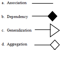
The components are:2. Aggregation

3.Dependency / Composition
4. Generalization
Generalization ( Bottom to Top ) means creating new sub classes from an existing class
Specialization ( Top to Bottom ) is the reverse process of generalization means creating new sub classes from an existing class
2) Example:
1.2.2 Object Diagram
1.3. Process
View
1.3.1 Activity
Diagram
Activity diagram shows the flow of events within our
system. The components are:
a)
b)
c)
Transition
d)
Decision Box
e)
Synchronization Bar
f)
Swim Lane
1.3.2 Sequence Diagram
Sequence diagram shows
the step to step what must be happen to accomplish a piece of functionality
provided by the system. The components are:
a) Activation
b) Object
c) Lifeline
d)
e) Focus
of Control
1.3.3
Collaboration Diagram
Collaboration diagram
displays object interactions organized around objects and their links to one
another. The components are:
a) Classifier role
b) Association role
c) Link
1.3.4 State chart Diagram
State chart diagram
show a life cycle of a single class. The state is a condition where the object
may be in. The components are:
a) Initial state
b) Final state
c) State
d) Transition
1.4 Implementation View
1.4.1 Component Diagram
Component is a smallest
individual physical replaceable part of the system. Component diagram shows the
organization and dependencies among software components. The components present
are:
a) Component
b) Dependency
1.5. Deployment View
1.5.1 Deployment Diagram
Deployment diagram
visualizes the distribution of components across the enterprise.
a) Note
b) Node Instance
c) Node


No comments:
Post a Comment